

Transient Load Steppers For Power Systems Test, and VRM & PDN Validation
GaN-based transient load steppers to support different current levels
- S10 P2105A Probe-Based Load Stepper – <10A
- S50 Probe – 10A-50A – Water-Cooled Probe Head Stepper
- S2000 – Up to 2000A – In-Socket Custom Load Board
The Picotest Transient Load Stepper is the fast programmable current-step instrument many engineers refer to as a ‘load slammer’ or ‘loadslammer’ — built to excite the impedance your VRM and PDN will actually see. Transient load current step testing is a critical part of power system design, test, and verification. No matter the architecture, design make-up, or power levels, transient testing is key to evaluating many aspects including power integrity, power distribution network (PDN) validation, Voltage Regulation Module (VRM) stability and transient response, noise, large-signal control loop stability, input filter stability, load emulation, thermal (TDP) testing, and IC package performance.
Picotest’s line of transient steppers enable testing of very fast load current transitions, high peak and average power, via multiple form factors that previously were unavailable or impractical to accomplish. In particular, demanding low-voltage, high-current applications including those found in data centers, AI, graphics, EV, and servers can now be tested, including crosstalk, thermal performance and EMI, long before the final ASIC is even available.

S10 P2105A Probe-Based Load Stepper – <10A
View the full webpage for S10 here.
- Browser probe style, swappable heads
- Up to 10A load current steps (peak)
- On and off control, user defined (at time of purchase) load current step, scales with power rail voltage
- Very high-power density
- High-speed excitation for tight spaces
- Custom-designed single resistor solution
- Wattage < 200W peak, <1W avg., Voltage 0.6V – 72V, < 10A
- Average power dissipation determines supported maximum duty cycle
What’s included
- S10 Transient Load Stepper Probe with single fixed load step (resistor value defined during checkout; additional probe tips available for purchase separately)
- P2105A Probe Handle with One (1) 1m SMA or BNC-Mini SMP PDN Cable®
Optional (available for purchase separately)
- S50DEMO Crosstalk Demo Board Add to Cart


S50 Probe – 10A-50A – Water-Cooled Probe Head Stepper
View the full webpage for S50 here.
- Browser probe style
- Up to 50A (peak and average), Voltage 0.6V–72V
- Direct control of load current profile, Six steps (defined at the time of purchase), scales with power rail voltage
- Enables infinite dwell time for slow load line loop testing and thermal (TDP) testing
- Verify large signal control loop stability
- Load emulation and transient testing for FPGA, AI, Big Data, Graphics and Servers
What’s included
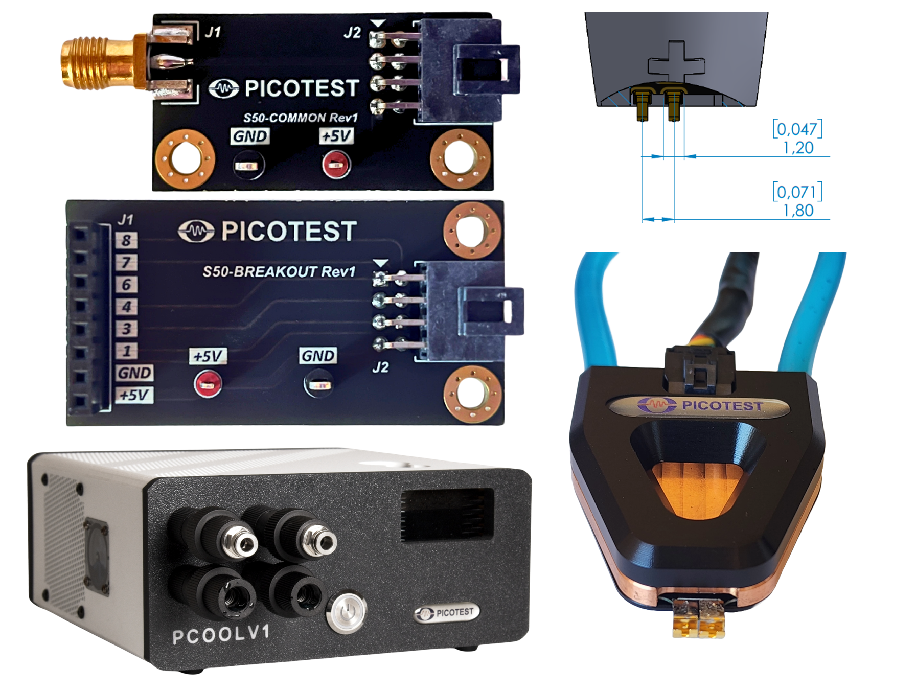
- S50 Water-Cooled Stepper Probe with six (6) customized load steps
- Cooling Tube
- Molex Cable
- PCOOLV1 Cooling Unit
- S50COMMON and S50BREAKOUT Controller Breakout Boards
Optional (available for purchase separately)
- S50DEMO Crosstalk Demo Board Add to Cart
S2000 – Up to 2000A – In-Socket Custom Load Board
- Custom Plug-In (Socketed) load board is developed in conjunction with your system/socket
- Up to 2000A (peak and average), Voltage 0.6V–72V
- Up to 512 ultra-high-speed load cells
- Up to 50MSPS 11-bit control
- Very high-power density supporting full power at DC for TDP and load line testing
- Custom application-specific load board or elastomer interface
- Up to 11-bit digital control
- Custom resistor design for high-speed and very high-power liquid cooling
- Load emulation and transient testing for AI, Big Data, Graphics and Servers –Sub-ns load cell (300MHz edge, up to 2000W Average), subject to interconnect inductance
- Water or refrigerated cooling
What’s included
- Customized Load Board with customized power delivery interface or elastomer interface
- Custom Controller Board
- Documentation consisting of register and bit mapping for controlling the step load and how to connect the digital controller to a PC, including cabling and GUI / terminal, etc.

Applications
- Power Supply Testing and Measurement
- VRM and PDN Validation
- Rail noise evaluation
- Transient load step (large signal)
- SPICE/ADS State Space Average Model Development
- Large-signal control loop stability and Input filter stability
- Thermal (TDP) testing
- IC Package evaluation

Transient Load Steppers
P2105A Browser Probe (Model S10)
| Characteristic | Rating |
|---|---|
| Edge Rate (R/F time) | <500ps switching * |
| Repetition Rate | DC-50MHz (Limited by average power and dwell time) |
| Control | User Supplied – 5V pulse generator |
| Maximum Dwell Time | 100us dwell |
| Input voltage rating | Based on custom resistor * |
| Output current rating | Based on resistor up to 10A |
| Wattage | <1W avg. |
| Voltage | 0.6V – 72V |
| Connector Type | SMPM pulse, spring tip |
* Final signal edge speed is dependent on the load board design, voltage, and current. Solution is single level (On/Off). Resistance is set at the time of manufacturing.
Water-Cooled Browser Probe (Model S50)
| Characteristic | Rating |
|---|---|
| Edge Rate (R/F time) | <500ps switching * |
| Repetition Rate | DC-50MHz (Limited by average power and dwell time) |
| Control | User Supplied – Digital logic generator or Micro-controller (3.3V or 5V) |
| Maximum Dwell Time | Up to 100% |
| Input voltage rating | Based on custom resistor * |
| Output current rating | Based on resistor up to 50A |
| Wattage | <50W avg. |
| Voltage | 0.6V – 72V |
| Connector Type | SMPM pulse, spring tip |
* Final signal edge speed is dependent on the load board design, voltage, and current. A 6-position water-cooled sub-ns browser step load probe. Resistance is set at the time of manufacturing. Any of the 6 resistors can be any value, they don’t need to be the same.
Crosstalk Demo Board (Model S50DEMO)
A single VIN with an input range from 4.5V to 20V is used to power both power domains.
| Characteristic | Rating |
|---|---|
| Power domain #1 | single phase output – 15A max – 0.85Vout |
| Power domain #2 | 4-phase output – 100A max – 1Vout |
Ultra-High Speed Step Loaders – In-Socket (Model S2000)
| Characteristic | Rating |
|---|---|
| Edge Rate (R/F time) | <500ps switching * |
| Repetition Rate | DC-50MHz (Limited by average power and dwell time) |
| Power level (continuous/instantaneous) | Up to 2047W Average, Voltage 0.6V–72V |
| Bandwidth – Duty Cycle/On/Off time range | UP to 100% Duty Cycle |
| Input voltage rating | Based on resistor, default is 0.8V |
| Output current rating | Based on resistor – up to 2047Amps |
| Current Resolution (steps) | Up to 11-bit (Up to 2047Amps in 1 Amp Steps) – 50MSPS logic driven pattern generation |
| Control | User Supplied – Digital logic generator, Micro-controller, or FPGA (3.3V or 5V) |
| Connector Types | (Load) User-Defined and Supplied – Fixed pattern or custom patterns available (Control) 16 pin Header |
| Model | Description | Price |
|---|---|---|
| S10 | P2105A Probe-Based Load Stepper < 10A Applications | Add to Cart |
| S10-TIP | P2105A Probe-Based Load Stepper – Probe Head Only | Add to Cart |
| S50 | Water-Cooled Head Stepper < 50A Applications | Add to Cart |
| S50DEMO | Optional for S10/S50: Crosstalk Demo Board | Add to Cart |
| S2000 | Load Board Development < 2000A Applications | Request a Quote |
Transient Testing
Transient load current step testing is a critical part of power system design, test, and verification. No matter the architecture, design make-up, or power levels, transient testing is key to evaluating many aspects including power integrity, power distribution network (‘PDN) validation, Voltage Regulation Module (‘VRM’) stability and transient response, noise, large-signal control loop stability, input filter stability, load emulation, thermal (TDP) testing, and IC package performance.
Picotest’s line of transient steppers enable testing of very fast load current transitions, high peak and average power, via multiple form factors that previously were unavailable or impractical to accomplish. In particular, demanding low-voltage, high-current applications including those found in data centers, AI, graphics, EV, and servers can now be tested, including crosstalk, thermal performance and EMI, long before the final ASIC is even available.
The power distribution networks that provide power to advanced digital loads such as CPUs, GPUs, ASICs, FPGAs, and other custom ICs can now be validated before the costly ICs are exposed to any power system-related unknowns.
Product Selection
The product line provides load step testing orders of magnitude faster and higher than previously available. Three product levels are available based on load current and delivery form factor: less than 10A, 10A-50A, and up to 2047A. Picotest offers both open and closed-loop load current control options. The open loop stepper is essentially a signal level voltage controlled switch that opens or closes a path from the power rail through a GaN FET and custom resistor. So, while the probe can be moved to rails of different voltages and the step current will vary based on the power rail voltage. The baseline load current is set at the time of purchase for a specified voltage-current combo resulting in fixed resistor values in the probe. The resolution is set by the resistor array Picotest offers up to 11-bit, 66MSPS control, emulating many different waveforms. Closed loop current control uses OPAMP feedback and custom, three-terminal sense resistors, allowing up to 100MHz analog bandwidth. The power density is much lower for closed-loop control than for open-loop control while the cost for closed-loop control is higher than for open-loop control.
The S10 under 10A solution is a hand-held browser-style probe format that fits into tight places. The open-loop current step is a single pre-defined (at the time of purchase) current step, determined by the custom resistor selection. Note, since this is an open loop stepper, the current is dependent on the voltage of the power rail. The S50 10A-50A solution is a water-cooled browser-style probe format with 6 user pre-defined current steps (6-bit logic level control). Again, the current is dependent on the voltage of the power rail.
The S2000 (up to 2047A) solution is provided as a custom in-socket, ASIC replacement. This is in the form of a PCB connecting to the customer’s power board through a custom interface. Picotest will work with you through the development process to achieve a solution with appropriate performance, control, and integration.
This step loader replaces the ASIC that normally loads the power rails, allowing thorough power rail validation including load line testing, large signal impedance, thermal testing, crosstalk assessment, and EMI. This solution allows programmed and custom load current profiles from 0 to 2047A average in 1 Amp steps and 66MSPS using an 11-bit controller and custom design GaN/resistor networks.
P2105A Probe-Based Load Stepper (S10)
This is a hand-held or probe stand-held probe that can be used to quickly step multiple rails. It has 2 pins (+/-) and is placed across the power rail. The current step is controlled by a control wire pair (5V 50 Ohm signal). The current step (current sinking into the positive pin) mimics the control signal.
Water-Cooled Browser Probe (S50)
This is also a hand-held or probe stand-held browser probe. It behaves in a similar way to the P2105A. It comes with a water-cooler that enables the load current/power density to be higher. The current step (current sinking into the positive pin) is controlled by a control wire pair. This is a 6-bit control bus with 3.3V or 5V logic level. There are 6 switches and each can be turned on or off and each can have a level set at the time of manufacturing. So, there are 6 discrete levels that can be switched individually or combined to achieve up to 50Amps.
Optional for S10/S50: Crosstalk Demo Board (S50DEMO)
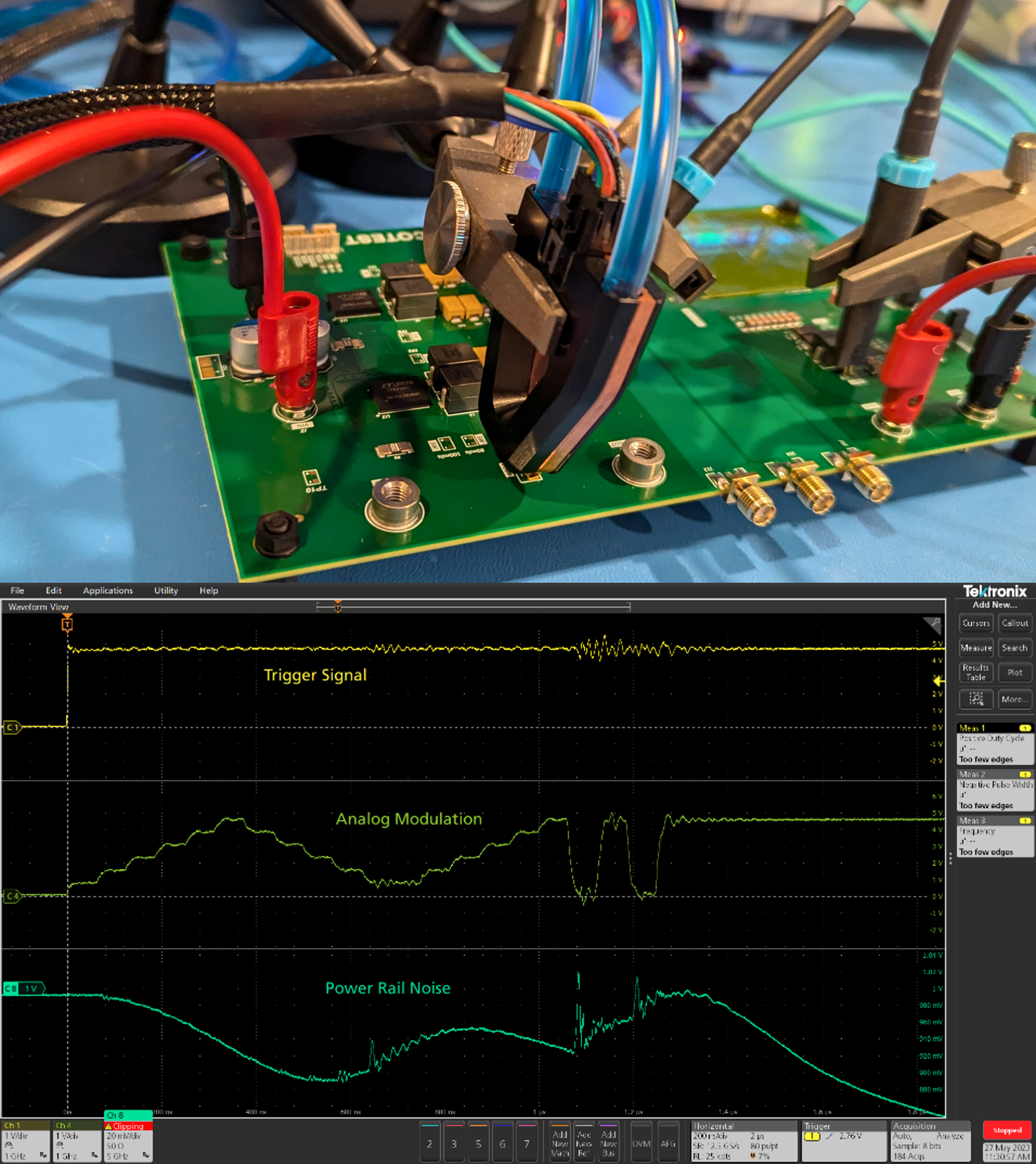
The Picotest S50 crosstalk demo board is a multi-layer PCB with 2 independent power domains to emulate crosstalk from an aggressor PDN to a victim PDN. In its most basic form of operation, the demo board enables transient load testing using the Picotest P2105A/S10 or S50 stepper probes to step the output load currents while viewing the voltage rail variations.
In addition, this 8-layer PCB has a 50mm x 50mm BGA footprint that is connected to both power domains to allow measurement of crosstalk between via structures. This PCB supports a single input voltage supply with 2 independent output voltages. Each power supply can be turned on or off independently of the other to allow engineers to assess the noise from each power domain.
This demo board is designed to support measurement with multiple Picotest probes and transient load stepper solutions. This demo board has probe points for the P2124A so engineers can measure PSRR on higher current PDN rails; P2104A/P2105A probe points to measure voltage; S10/S50 probe points to support testing with Picotest transient load steppers.
Custom Load Board Development (S2000)
This is generally a full custom solution. It consists of a power board that is designed and fabricated in a BGA pattern to be able to load the power board as ASIC package speed. The Picotest load board circuitry can be integrated onto your board or configured as a daughter card that mates with your power board directly or through a custom elastomer/connector interface. Each supply point is driven by one or more GaN cells which are essentially switches that can be configured to any voltage. The load current delivered can be modulated in just about any way with a custom 11-bit controller to drive the GaN cells on and off at up to 66MSPS. The specifications of the rates, speeds, and current/power levels are shown in the detail specification section.

350MHz Pseudo Random Load Current Pattern
Picotest GaN Load Stepper Technology
Picotest’s line of load steppers utilize custom GaN technology and innovative power delivery interconnect formats and cooling to meet the requirements of supplying step load currents. Power levels up to 2000 Amps, 2000W average power (125W-125A/in2), up to 100% duty cycle, load current step rates that are sub-ns (<500ps), with DC – 50MHz repetition rates. These edge rates and average power levels exceed current capabilities by orders of magnitude.
The Picotest load steppers solve several pressing hurdles for power integrity testing. Electronic loads are too slow and present too much capacitance to allow a valid measurement to take place. Their edge rates are too slow to address the bandwidths needed to test PDN performance. They are unable to achieve the average and peak power levels needed. Additionally, the overly inductive interconnections between industry-standard load step generators also make them too slow.
To achieve these performance breakthroughs, Picotest pushed the limits of GaN density, developed custom resistors, developed advanced cooling techniques, and integrated high-speed digital control. The result is a miniaturized load cell that can be replicated and scaled from a single cell to an array of 512 load cells in a 100mm x 100mm socket. Various form factors including novel probe heads were developed to allow load step testing on a rail-by-rail basis. Key to getting the edge rates necessary to test the high bandwidths associated with low voltage PDNs was the reduction to near-zero inductance of the interconnect between the steppers and the PCB where the load step is applied. Given the minimization and very high power densities, custom water and refrigerated cooling schemes were also implemented. Due to the varied nature of the power system architectures, care was taken to allow most of these features to be customized to application requirements.
New techniques to minimize interconnect inductance, allowing fast-edge (<500ps) transient load currents to be delivered to the power supply rail include browser probes, water-cooled probes, and custom-developed load boards.
Application Notes
Evaluating Voltage Regulator Stability Using Step Load Testing
Transient Load Steppers
Picotest Transient Load Stepper Demonstration
Live at DesignCon 2024: watch the Transient Load Stepper in action (live demo starts at 3:55). DesignCon came with a lot of talk about 800 Amps, 1000 Amps, 2000 Amps. The Load Stepper was here for the high power folks, and if you are a data center engineer looking to test your power rails ahead of the delivery of the ASIC, this is the tool you need. Listen to Steve Sandler discuss and watch a live demo of the product.
Tektronix and Picotest Showcase the 2000A Transient Load Stepper
During APEC 2025, Steve Sandler from Picotest showcased their latest 2000 A transient load stepper—a powerful emulator for AI server design. Engineers can use it to evaluate their power system designs for current-hungry GPUs, before they even have chips. With Tektronix probes and the 6 Series MSO Oscilloscope, the demo revealed precise insights into cross talk and ground bounce. A standout moment for optimizing high-performance systems!