
S50 Probe
The S50 enables very fast load current transitions with high peak and average power. The special probe head design brings the step right onto your board, eliminating interconnect inductance for sub ns switching times. In particular, demanding low-voltage, high-current applications including those found in data centers, AI, graphics, EV, and servers can now be tested, including crosstalk, thermal performance and EMI, long before the final ASIC is even available.
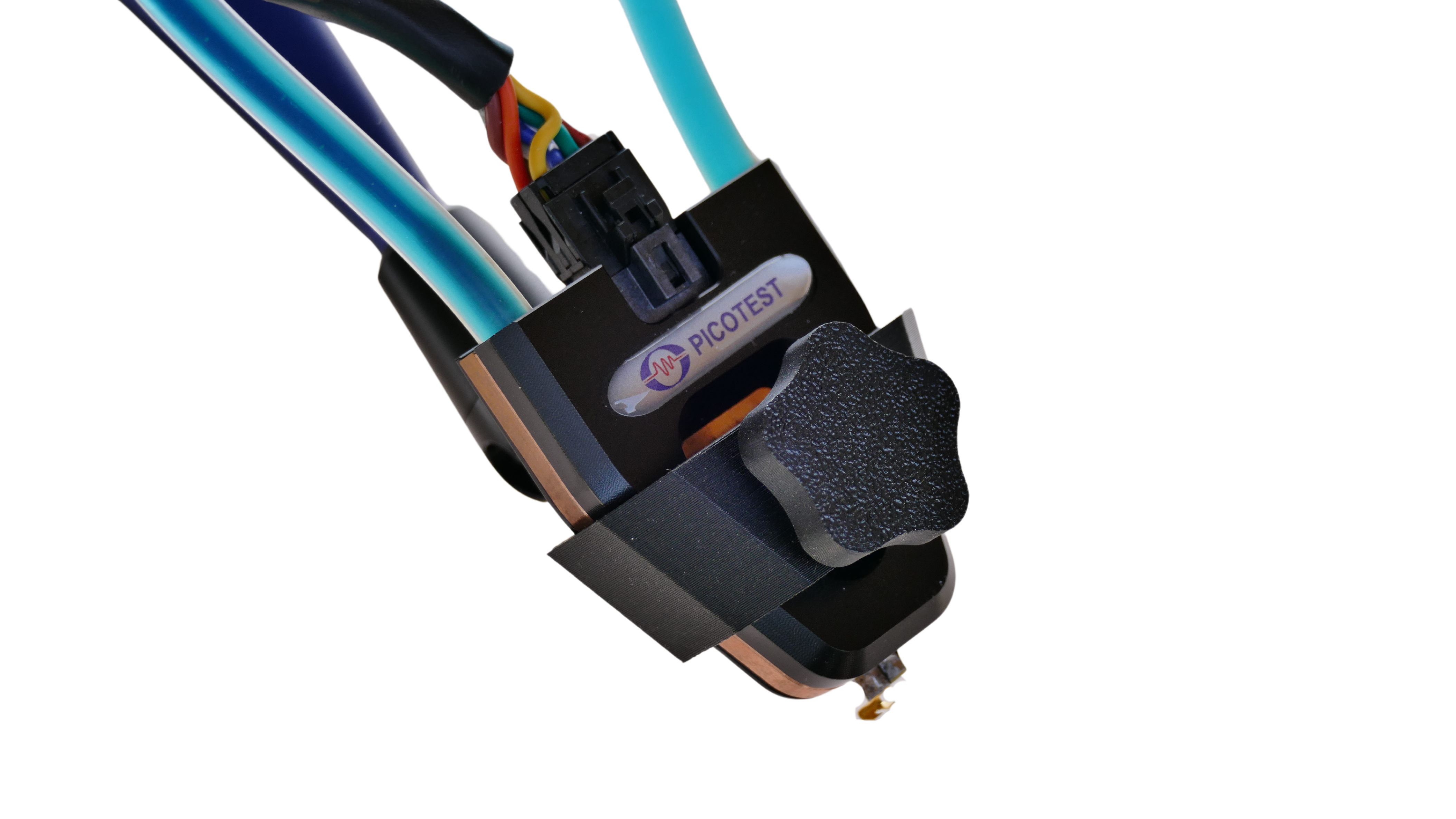
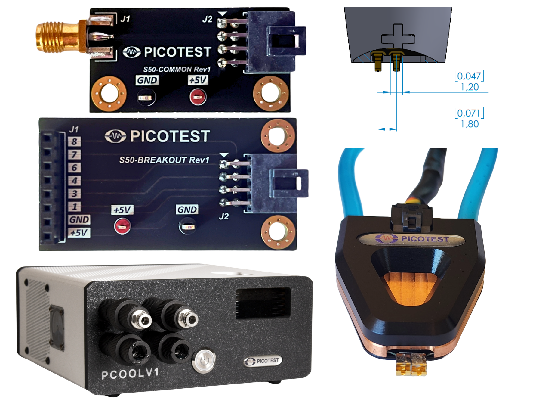
The S50 probe can be used to perform transient load current step testing up to 50A. It uses a water-cooled browser-style probe format with 6 user pre-defined current steps (6-bit logic level control). The current step (current sinking into the positive pin) is controlled by a set of control wires. This is a 6-bit control bus with 3.3V or 5V logic level (Molex connector seen in the image to the right at the top). Each current switch in the head can be turned on or off and each can have a level set at the time of manufacturing. So, there are 6 discrete levels that can be switched individually or combined to achieve up to 50Amps. You have full open loop control of when each switch is opened or closed. The current levels are dependent on the voltage of the power rail and sized based on six resistors predefined at the time of purchase. If the voltage of the power rail changes, the resulting load currents will move commensurately (Ohm’s law).
Key Features
- High-speed load current pulse in a Browser probe style
- Up to 50A (peak and average), Voltage 0.6V–72V
- GaN-enabled–Orders of magnitude faster edge speeds than other solutions, nS load steps possible
- Direct control of load current profile, Six steps (defined at the time of purchase), scales with power rail voltage
- Water-cooled, Very high-power density
- Custom-designed six (6) resistor solution
- 100% Duty Cycle. Enables infinite dwell time for slow load line loop testing and thermal (TDP) testing
- High speed load current pulse, < 500ps Switching
- Wattage < 50W average/peak
- GaN-enabled–Orders of magnitude faster edge speeds than other solutions, nS load steps possible
Benefits/Applications
- High-speed excitation for tight spaces
- Load emulation and transient testing for FPGA, AI, Big Data, Graphics and Servers
- Power Supply Testing and Measurement
- VRM and PDN Validation
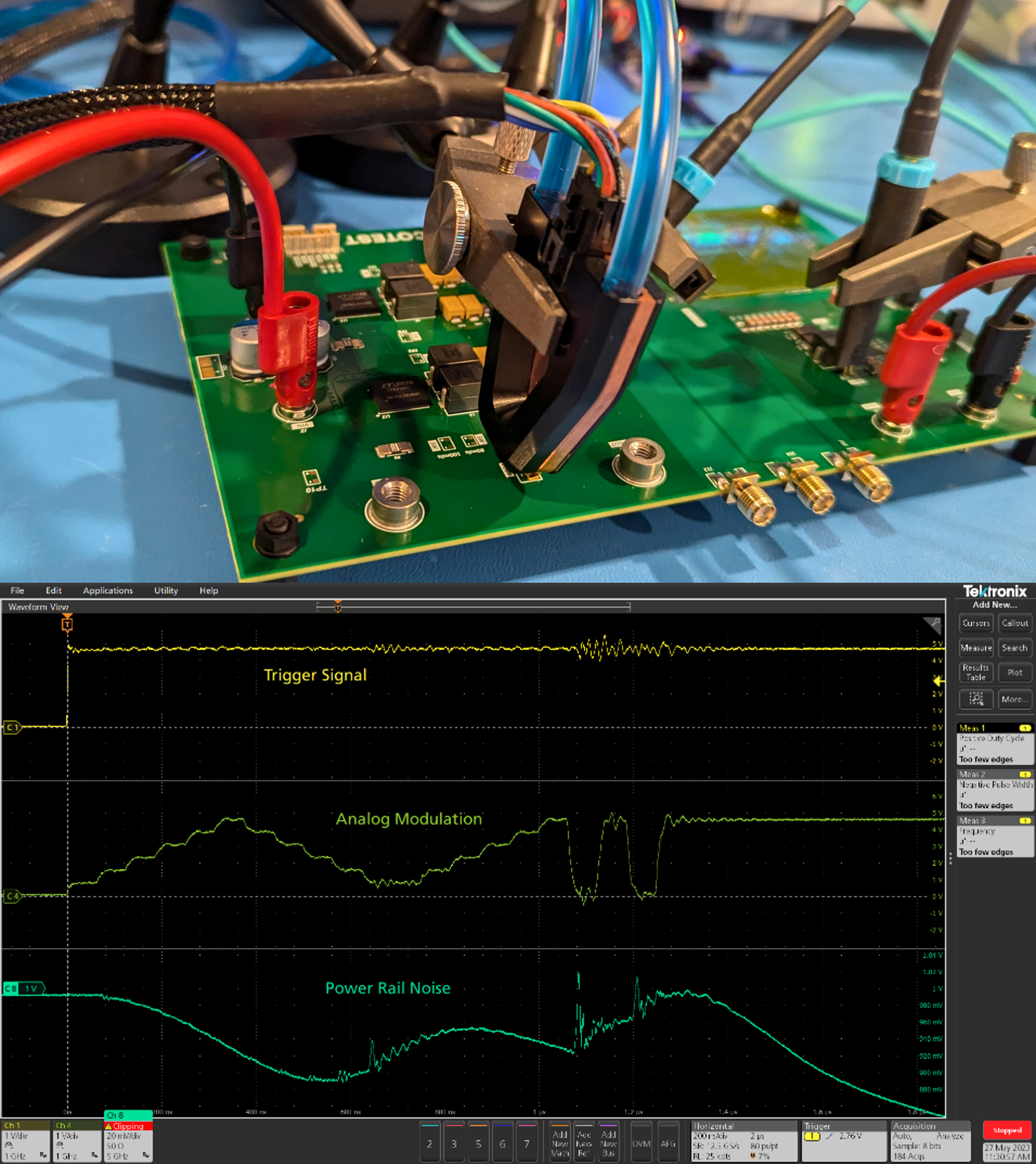
- Rail noise evaluation
- Transient load step (large signal)
- SPICE/ADS State Space Average Model Development
- Verify large signal control loop stability. Pairs with SEPIA
- Thermal (TDP) testing
- IC package evaluation
Picotest S50 Crosstalk Demo Board
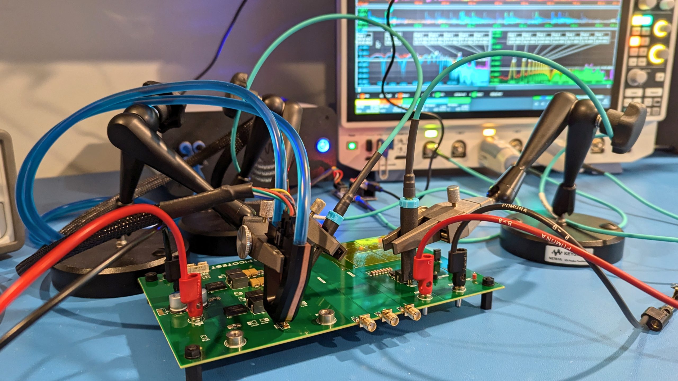
The Picotest S50 crosstalk demo board is a multi-layer PCB with 2 independent power domains to emulate crosstalk from an aggressor PDN to a victim PDN. In addition, this 8-layer PCB has a 50mm x 50mm BGA footprint connected to both power domains to allow measurement of crosstalk between via structures. This PCB supports a single input voltage supply with 2 independent output voltages. Each power supply can be turned on or off independently of the other to allow engineers to assess the noise from each power domain.
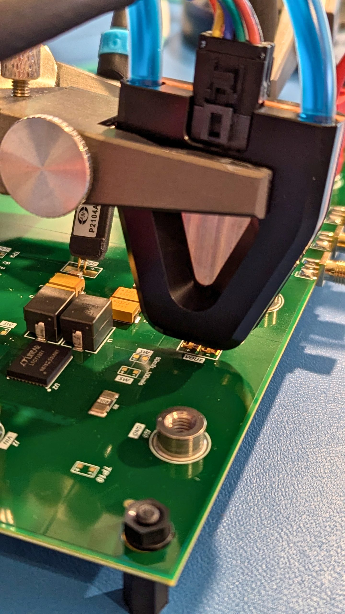
This demo board is designed to support measurement with multiple Picotest probes and transient load stepper solutions. It has probe points for the P2124A, so engineers can measure PSRR on higher current PDN, P2104A/P2105A probe points to measure voltage, and S10 and S50 probe points to support testing with the Picotest transient load steppers.
This demo board can also be used to do PDN impedance measurements with the Picotest P2102A 2-port probe.
Crosstalk Demo Board Specs:
A single VIN with an input range from 4.5V to 20V is used to power both power domains.
Power domain #1 – single phase output – 15A max – 0.85Vout
Power domain #2 – 4-phase output – 100A max – 1Vout
What’s included
- S50 Water-Cooled Stepper Probe with six (6) customized load steps
- Cooling Tube
- Molex Cable
- PCOOLV1 Cooling Unit
- S50COMMON and S50BREAKOUT Controller Breakout Boards
The S50 probe comes with a water cooling pump, a control cable (black) and two breakout boards for simplified load step control.

S50 Probe
| Characteristic | Rating |
|---|---|
| Edge Rate (R/F time) | <500ps switching * |
| Repetition Rate | DC-50MHz (Limited by average power and dwell time) |
| Control | User Supplied – Digital logic generator or Micro-controller (3.3V or 5V) |
| Maximum Dwell Time | Up to 100% |
| Output current rating | Based on resistor up to 50A |
| Input Voltage Rating | Based on custom resistor * |
| Wattage | < 50W avg. |
| Voltage | 0.6V – 72V |
| Connector Type | SMPM pulse or spring tip |
* Final signal edge speed is dependent on the load board design, voltage, and current. A 6-position water-cooled sub-ns browser step load probe. Resistance is set at the time of manufacturing. Any of the 6 resistors can be any value, they do not need to be the same.
Crosstalk Demo Board Specs:
A single VIN with an input range from 4.5V to 20V is used to power both power domains
Power domain #1 – single phase output – 15A max – 0.85Vout
Power domain #2 – 4-phase output – 100A max – 1Vout
| Model | Description | Price |
|---|---|---|
| S50 | Water-cooled Transient Load Stepper Probe Head (< 50W avg) with 6 customized load steps, cooling tube, Molex cable, PCOOLV1 Cooling Unit, S50COMMON and S50BREAKOUT Controller Breakout Boards. | $8,500.00 Add to Cart |
| S50DEMO | Crosstalk Demo Board | $795.00 Add to Cart |
The S50 (up to 50A) load stepper in a probe is used to perform transient load current step testing. The S50 provides load step testing orders of magnitude faster and higher than previously available. The open loop stepper (closed loop optional) is essentially a signal level voltage controlled switch that opens or closes a path from the power rail through a GaN FET and custom resistor. So while the probe can be moved to rails of different voltages, the step current will vary based on the power rail voltage.
A molex connector with an eight (8)-wire breakout cable is also plugged into the back of the head. The S50 probe comes with two breakout boards. One board (S50COMMON) turns on and off all load current levels together. The second board (S50BREAKOUT) allows control of each load current switch individually. However, any form of control system can be used to control the probe current levels (function generator, Arduino, etc.).
Please see the following download for more information.
Water-Cooled Browser Probe (S50)
The probe head is connected to a water pump for cooling. The probe head itself comes with spring tips (or solder tabs optional) to facilitate connection to pads on the PCB.

