
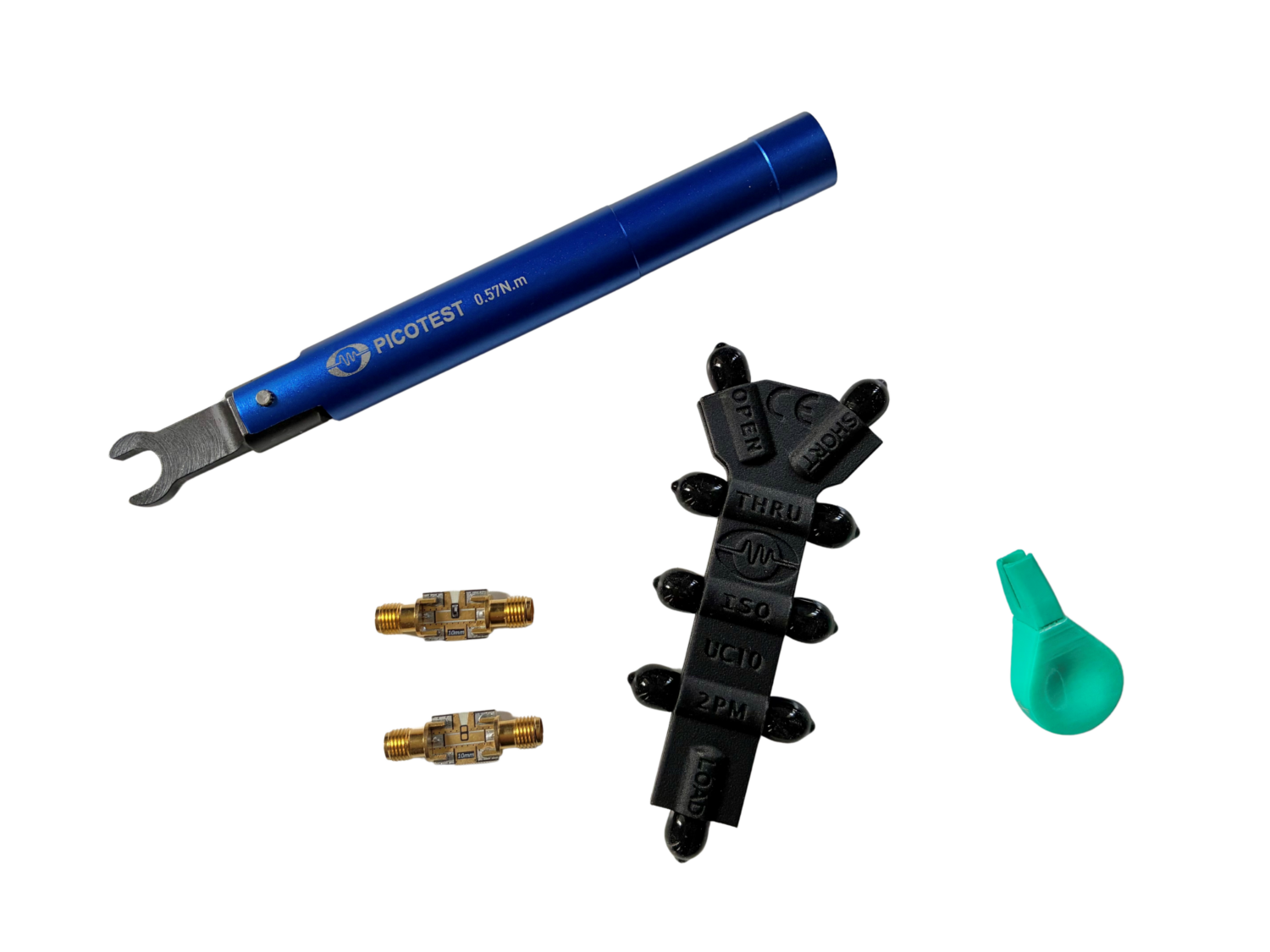
UC10 Universal 6-Way Calibrator
Benefits
The Picotest UC10 3.5mm Universal 6-Way Calibrator enables the highest accuracy 1- and 2-port measurements for the OMICRON Lab Bode 100 and Bode 500, as well as supporting calibration for other traditional VNAs.
- Enables accurate passive component measurement
- Results accurate to several pH (<10pH) for Bode 100/500 VNA
- Works with all VNAs including Keysight E5061B, Rohde & Schwarz ZNL/ZNB, and Copper Mountain S Series
- Supports essential calibration accuracy when performing component characterization tests
- S parameter and Z (impedance) calibration
- Simultaneous calibration and de-embedding using matching board mounts
- Supports 1-port reflection and 2-port shunt through measurements
- Stable, accurate, and repeatable measurements – Built on precision controlled dielectric material, with multiple controlled parameters
- The most accurate component measurement solution for OMICRON Lab Bode 100 and 500 users
Key Features
- Allows accurate measurement without a calibration kit using matched component mounting boards.
- Accurate calibration standard for the Bode 100 and Bode 500 VNA 2-port shunt through impedance testing
- Enables accurate phase response required for SPICE Modeling features
- Supports S/Z domain calibration for use with all VNAs
- Includes 1-Port SHORT, OPEN, and LOAD
- Includes THROUGH (used also for 2-port OPEN)
- Includes 2-Port ISO-SHORT (for uOhm and fH impedance floor)
- Includes 2-Port MATCH
- (Typical) Data-based calibration file (aka Cal-Kit) for traditional VNA calibration
- DC-3 GHz Frequency Range *. Supports full frequency range of Bode 100/500.
- The Calibrator board supports a wide variety of part sizes (0201 – 7343) using our matching mounts. Custom board sizes are available for order.
* based on a data based cal-kit, S-parameter data is available for the UC10.

What’s included
The UC10 3.5mm Universal 6-Way Calibrator includes a blank calibration board for mounting your parts, as well as an example board containing 1.2nH inductors (that can be reused). A torque wrench is also included so that the proper calibrated torque can be applied to the connectors.
- UC10 3.5mm calibrator board
- Calibrated torque wrench
- Matching component mount with 1.2nH + 100pH (8%) chip inductor (board can be re-used)
- One (1) blank test board
- Board holder
- One (1) Year Manufacturer’s Warranty


UC10 Universal 6-Way Calibrator
Detailed Specifications
| Characteristic | Rating |
|---|---|
| Connector | 3.5mm Female |
| Frequency Range | DC-3GHz |
| State | OPEN |
| Typical delay (ps) | 65.0 |
| State | SHORT |
| Typical delay (ps) | 66.0 |
| BODE SHORT Delay | 8ps |
| LOAD Return Loss (dB) | ||||
|---|---|---|---|---|
| 50 MHz | 450 MHz | 1 GHz | 3 GHz | |
| Typical | 62.9 | 47.7 | 36.4 | 25.8 |
| Minimum | 57.4 | 38.8 | >30 | 19.8 |
| DC Resistance | 50 +/- 0.05 Ω |
| Max Power Rating | 125mW |
| THROUGH Phase Delay (degrees) | ||||
|---|---|---|---|---|
| 50 MHz | 450 MHz | 1 GHz | 3 GHz | |
| Typical | 140.0 | 132.1 | 135.2 | 131.0 |
| THROUGH Return Loss (dB) | ||||
|---|---|---|---|---|
| 50 MHz | 450 MHz | 1 GHz | 3 GHz | |
| Typical | 44.67 | 37.30 | 29.10 | 26.23 |
| THROUGH Insertion Loss (dB) | ||||
|---|---|---|---|---|
| 50 MHz | 450 MHz | 1 GHz | 3 GHz | |
| Typical | 55.5 | 0.0022 | 0.0520 | 0.1475 |
| ISO-SHORT Insertion Loss (dB) | ||||
|---|---|---|---|---|
| 50 MHz | 450 MHz | 1 GHz | 3 GHz | |
| Typical | 72.0 |
| DUT Mount Time Delay (ps) | ||||
|---|---|---|---|---|
| 50 MHz | 450 MHz | 1 GHz | 3 GHz | |
| Typical | 145.0 | 137.2 | 135.2 | 135.9 |
Power rating, max. LOAD – 125 mW
Weight, approx.: 20 g
Dimensions, approx.: 1.5” x 3.75” x 0.45”
Environmental conditions Operating temperature: -10 °C to +55 °C
UC 10 Connectors
The 3.5mm connector is similar to a higher-quality SMA. The key difference lies inside: the 3.5mm connector uses an air dielectric. This eliminates the performance inconsistencies associated with the Teflon interface in SMAs. Furthermore, its outer conductor wall is thicker, giving it superior mechanical strength and durability. This makes the 3.5mm connector a favorite for laboratory and test applications where repeatable measurements are paramount and better performance up to 34 GHz. It is safe to mate with SMA and 2.92mm connectors (Group 1 (1/4-36UNS Thread): SMA, 3.5mm, 2.92mm).
Ground loop isolation:
To remove the ground loop in the 2-port measurement setup a ground loop isolator is necessary. Picotest make a number of these devices in the J2102B, J2113A, J2114A or J2115A.
| Model | Description | Price |
|---|---|---|
| UC10 | Universal 6-Way Calibrator, 3.5mm. Includes calibrated torque wrench, matching component mounts (1 with 1.2nH and one blank), and board holder. | Add to Cart |
The Picotest UC10 3.5mm Universal 6-Way Calibrator enables the highest accuracy 1- and 2-port measurements for the OMICRON Lab Bode 100 and Bode 500, as well as supporting calibration for other traditional VNAs.
It consists of the UC10 Calibration board with a matching (size) calibration board (mounting PCB). The UC10 pairs with the Bode Suite’s Full-Range or User Calibration feature for component test and characterization. It enables the new Bode Analyzer Suite SPICE Modeling features as well, given it allows proper magnitude and phase measurement, essential for accurate SPICE model generation and measurement to simulation correlation.
The UC10 works from DC-3 GHz with 3.5mm female (50 Ω) connectors. It is characterized by very low return and insertion loss values over the entire operating frequency range from DC to 3 GHz. Both 1-port and 2-port calibrations are supported for both S domain and Z domain.

The Bode 100 and Bode 500 VNAs employ non-traditional Z-Domain (Impedance) calibration without support for known calibration kits. This method allows a much simpler process using only 3 calibrations, 2-port OPEN (THROUGH as marked on the Calibrator), 2-Port Load (2PM), and 2 Port Iso-Short (ISO-SHORT). This calibrator is utilized with the existing Bode 100/500 calibration dialogs.
The Iso-Short is the most complex, requiring both ground loop correction and an ‘ideal’ short. Lacking port extensions or Automatic Fixture Removal (AFR) support, de-embedding the mounting PCB is best accomplished by making the component mounting board match the calibrator, which in the case of the provided Picotest mounting PCBs, they do. Precise fabrication and material control of the calibrator and the associated component DUT mounting board impedance and time delay assure accurate measurement and de-embedding. This is how the UC10 achieves the phase accuracy and the uOhm/fH impedance floor.
Bode VNA Usage
The Bode 100/500 VNAs do not offer calibration kit support. They do not use SOLT or SOLR calibration for 2-port measurements. And they don’t offer port extensions, fixture removal or embedding/de- embedding. However, the Bode 100/500 uses a Z parameter calibration, that is more direct and accurate up to its full bandwidth, 450MHz.
Therefore, the lack of Cal-Kit support requires that users calibrate the measurement differently. A traditional VNA such as the Keysight E5061B, or the R&S ZNL/ZNB uses 8 calibrations to create accurate 2-port impedance measurements at the cable connectors. The DUT mounting board is then de-embedded (removed) using Port Extensions or Automatic Fixture Removal.


To perform a calibration with the Bode 100/500 you
- Connect the UC10 in a 2-port shunt through test configuration.
- Perform the Open calibration with the UC10 connected at the THROUGH connectors
- Perform the Short calibration with the UC10 connected at the ISO-SHORT connectors
- Perform the Load calibration with the UC10 connected at the Bode-LOAD connectors
- Connect and measure your component using the supplied mounting board.


Bode 100/500 Example Measurement

In summary, the UC10 calibrator offers all necessary calibration standards in one handy unit. It is the optimal solution for complete calibration of a network analyzer. With precision matched mounting boards the calibration and de-embedding of the printed circuit boards are performed simultaneously for either S parameter or Z parameter supported methods.
The UC10 calibrator can be used with the E5061B for either full 2-port calibration or impedance calibration. When using the precision matched component mounting boards the mount can also be de-embedded at the same time. For full 2-port calibration:
- Select full 2-port calibration
- Perform port 1 OPEN, SHORT and LOAD calibrations using the SOL connectors on the UC10 calibrator.
- Perform port 2 OPEN, SHORT and LOAD calibrations using the SOL connectors on the UC10 calibrator.
- Using a blank mount (no component) perform a Flush THROUGH calibration
- Connect and measure the mounted component on the matching component mount.
For impedance calibration
- Create or select an ideal cal kit
- Select impedance calibration for 2-port shunt through
- Perform OPEN (Through)
- Perform Short (Iso-short)
- Perform 2 port Load (2PM)
- Connect and measure the mounted component on the matching component mount.
So long as the components to be measured are mounted on the matching PCB, the results will be correct with the PCB de-embedded. The component measurement still includes its own electrical length, which also needs to be removed for EM simulation.
1.2nH Inductor Characterization
The UC10 calibration kit includes a blank component mount and a 1.2nH +/- 100pH mounted chip inductor for confidence testing. Testing results for the inductor are shown below.


Typical Specifications
See UC Specifications and Statistics.xlsx
Weight, approx.: 20 g
Dimensions, approx.: 1.5” x 3.75” x 0.45”
Environmental conditions Operating temperature: -10 °C to +55 °C
UC 10 Connectors
The 3.5mm connector is similar to a higher-quality SMA. The key difference lies inside: the 3.5mm connector uses an air dielectric. This eliminates the performance inconsistencies associated with the Teflon interface in SMAs. Furthermore, its outer conductor wall is thicker, giving it superior mechanical strength and durability. This makes the 3.5mm connector a favorite for laboratory and test applications where repeatable measurements are paramount and better performance up to 34 GHz. It is safe to mate with SMA and 2.92mm connectors (Group 1 (1/4-36UNS Thread): SMA, 3.5mm, 2.92mm).
Ground loop isolation:
To remove the ground loop in the 2-port measurement setup a ground loop isolator is necessary. Picotest make a number of these devices in the J2102B, J2113A, J2114A or J2115A.