Ensuring optimal performance in electronic systems requires precise measurement of Power Distribution Network (PDN) impedance. Accurate impedance measurements help identify potential issues such as high-Q impedance resonances, poor control loop stability, or the potential for noise within the power delivery path. Picotest offers specialized transmission line ‘browser’ probes, notably the P2102A and P2105A, designed to facilitate these critical measurements. This article provides a step-by-step guide to setting up your PDN impedance measurement using these probes.
Understanding PDN Impedance Measurement
PDN impedance measurement involves testing the AC impedance at different locations along the power supply voltage rail path. Low and flat impedance across a broad frequency range is typically desired to ensure stable voltage delivery to the load ICs. Elevated impedance, or impedance resonances with high Q, at certain frequencies, can lead to voltage fluctuations, affecting the performance of sensitive electronic circuits.

The key item to note is that testing at different points along the power path and for different levels of impedance magnitude, and for different frequency bands, requires different equipment and techniques. They are not all discussed here but we are happy to provide reference material and tutorial videos.
Equipment Required
To perform PDN impedance measurements effectively, the following equipment is necessary:
- Picotest P2102A 2-Port Probe: This is a unique, specially designed 2-port probe (4-pin kelvin) ideal for measuring power supply impedance and stability. It can test down to sub-milliOhm levels. Often left out in Power Integrity (PI) assessments, the power supply’s (or VRM’s, as it’s sometimes called), impedance levels surprisingly impact the PDN impedance at frequencies well above the regulator’s bandwidth. The P2102A is ideal for browsing and testing the VRM’s quality, especially when there are numerous rails present. It is faster and more accurate than Bode plot testing, both in terms of test setup ease and the usefulness of the information that results from the test.
- Picotest P2105A (1-Port) Probes: At the load end of the PDN, vias can get in the way of using the P2102A probe for impedance testing. Small pad sizes and the fact that it can be difficult to find 2 power rail/2 ground points right next to each other means we need a different approach. A pair of P2105A high-bandwidth probes is perfect for a 2-port impedance test at the load. You can probe on the same or opposite sides of the PCB with great precision and high bandwidth.
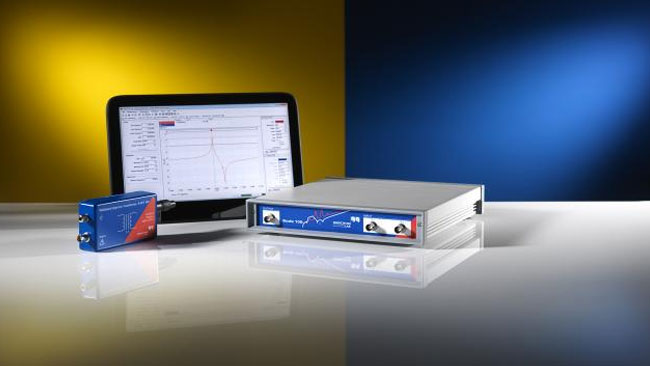
- Vector Network Analyzer (VNA): A frequency domain test instrument, either in the form of a dedicated VNA or an oscilloscope with frequency response features, is essential. All of the Picotest probe options work with any VNA or oscilloscope. Along with the popular OMICRON Lab Bode 100 and 500 VNA, Picotest sells and supports a variety of options from Keysight, Copper Mountain, Tektronix, Rohde & Schwarz, and others.
Step-by-Step Setup Guide
- Select the Appropriate Probe Tips
- The P2102A comes with four probes tips corresponding to 0402, 0603, 0805, and 1206 component sizes. The P2105A probes come with one probe tip size, but others probe heads can be purchased and snapped on. Pitch sizes of 20, 31, 40, 50, 60, 70, 80, 100, and 150 mils, as well as GSG/SMA are available. It is recommended that an unpopulated pad be probed. If a blank pad is not available, a component can be removed to provide a landing pad for the probe. You can probe on top of a component, but you may need a larger pitch probe head to accomplish the straddling of the component depending on its height, and it will impact the results. Greater care in this case is needed and a probe holder like the Picotest 3DPP-200 Probe Holder Set is invaluable.
- Connect the Probes to the VNA
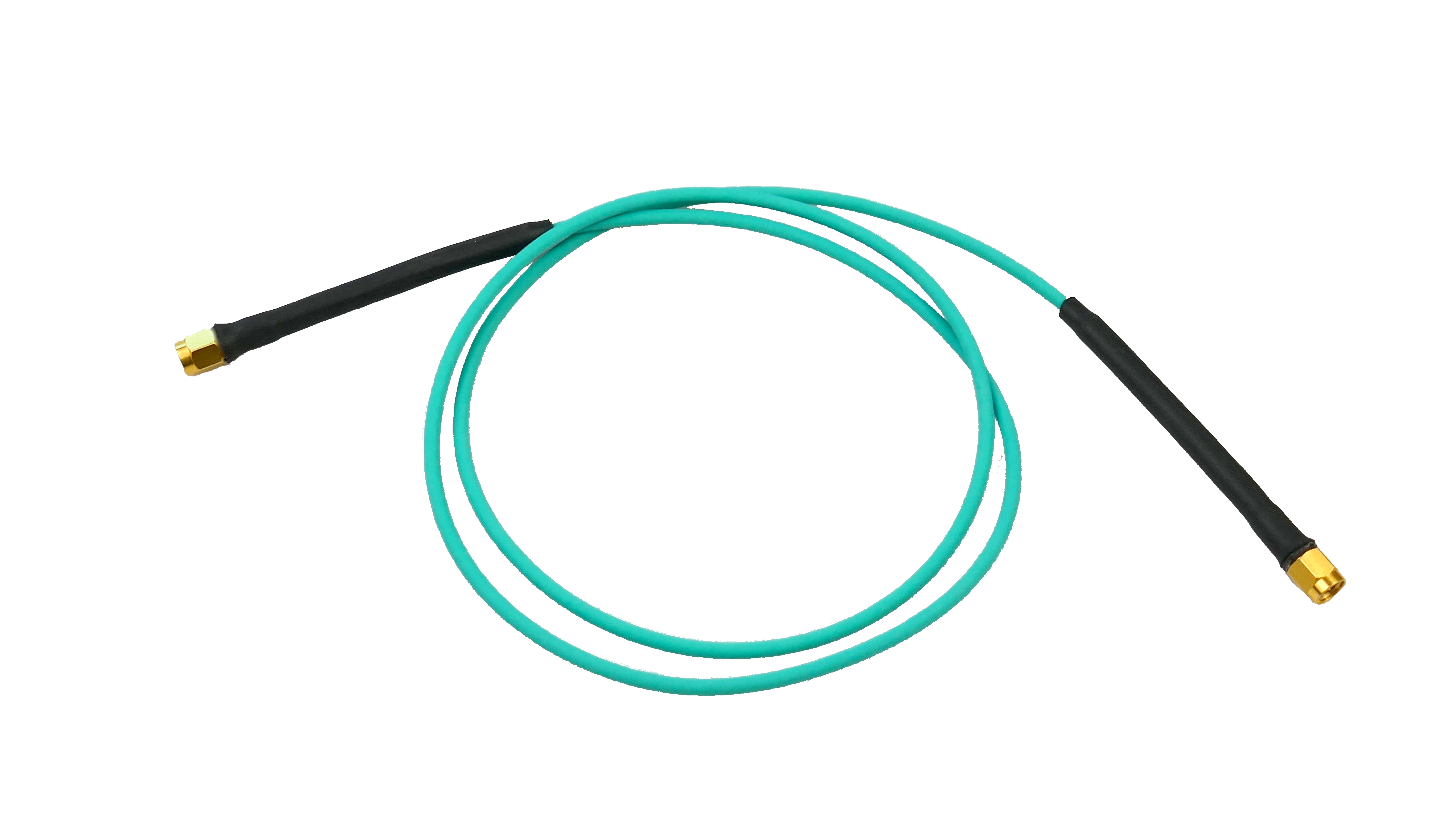
- Connect the P2102A or two P2105A probes to the VNA’s ports, using high-quality coaxial cables such as Picotest PDN cable. A setup diagram and instructions are shown in the Power Supply and Power Integrity Training Exercise Booklet (link below).
- Calibrate the VNA
- Perform calibration to account for systematic errors and ensure measurement accuracy. There are various videos on this topic. Here are two:
- Bode 100/500 Calibration – 2-Port Shunt Through Impedance Calibration with Bode 100 and P2102A https://youtu.be/PwEUQbPXKsA
- Other VNA Calibration Picotest P2102A 2-Port Calibration with CMT VNA https://www.youtube.com/watch?v=8-yHb5QPAoU&t=8s
- Note: Calibration may not be available in oscilloscopes. It is certainly okay to try the test without calibration as well to see the improvements that calibration can bring.
- Prepare the Device Under Test (DUT)
- Ensure the DUT is powered appropriately and accessible for probing.
- Identify the test points on the DUT where impedance measurements will be performed.
- Perform the Measurement
- Carefully position the probe tips on the selected test points, ensuring firm and stable contact.
- Initiate the measurement sequence on the VNA or oscilloscope, capturing the impedance data across the desired frequency range.
- Analyze the Results
- Review the impedance plot generated by the VNA or oscilloscope to identify any anomalies or areas of concern.
- Compare the measured impedance against design specifications to assess performance.
Conclusion
Accurate PDN impedance measurement is crucial for ensuring the reliability and performance of electronic systems. By utilizing Picotest’s P2102A and P2105A probes in conjunction with a calibrated VNA, engineers can effectively assess and optimize their power distribution networks. Adhering to best practices during setup and measurement will further enhance the precision and reliability of the results.
You can use the Exercise Booklet 2-Port Probe Output Impedance (Page 59) to understand the test setup. You don’t need to have the VRTS3 demo board per se; the test setup is the same for your PDN measurement.
Further Details and Support
- Application Note: 2-port Impedance Measurement using the P2102A Probe and Bode 100 VNA
- Download: Power Supply and Power Integrity Training Exercise Booklet (pictured below)
- Download: Bode 100/500 Setup files for the Exercise Booklet
- Note: This is a zip file containing the Bode VNA Setup files. Please change the extension from .txt to .zip.