
Impedance testing is a fundamental aspect of electronic circuit design, especially when dealing with power delivery networks (PDNs), low-dropout regulators (LDOs), voltage references, and power converters. With various test methods and tools available, understanding which technique to use and when is crucial for accurate results.
In this ultimate guide, we will explore every way to test impedance, including 1-port, 2-port, and 3-port measurements, while also providing keynotes on voltages, equipment, and limitations.
Impedance Testing for Power Supply Components
Impedance testing is essential for analyzing components like LDOs, linear regulators, point-of-load (POL) converters, and DC-DC converters. Each of these components can be tested using different approaches depending on the test requirements, voltage levels, and impedance values.
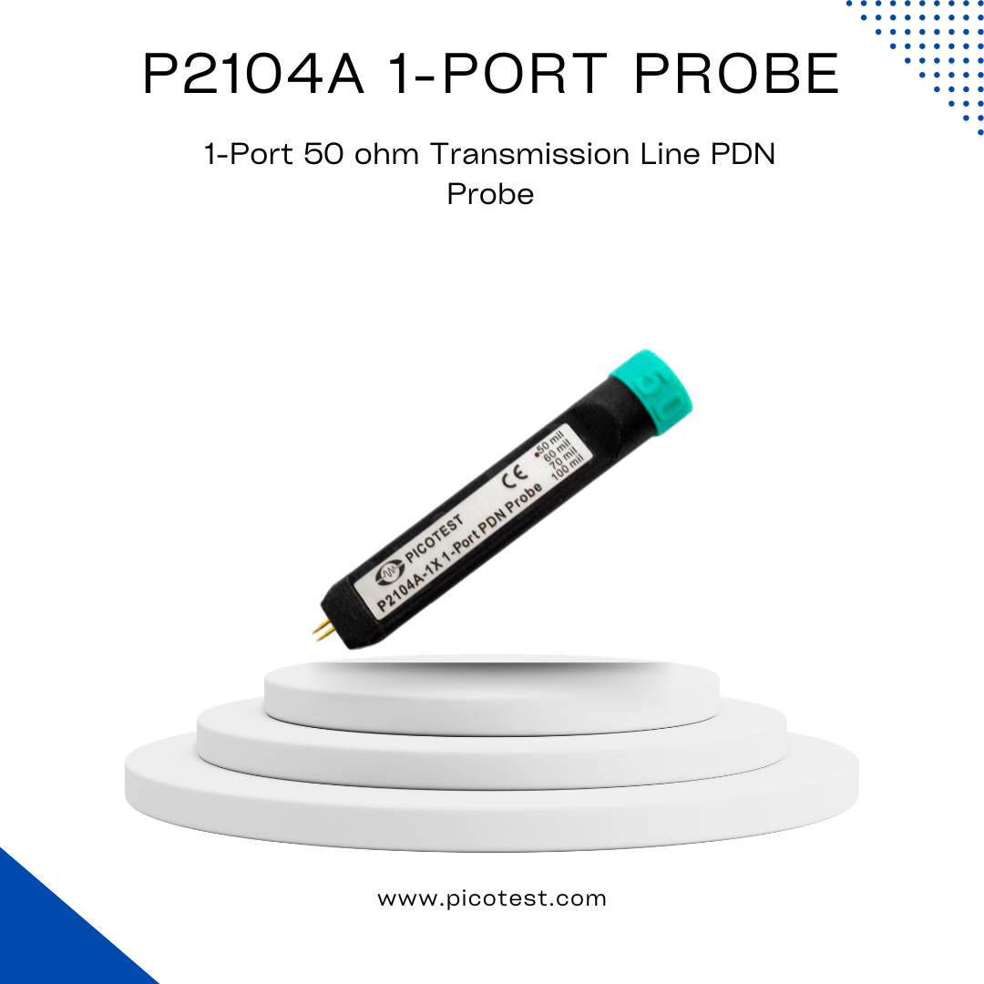
- 1-Port Measurements: Often used for very low-power LDOs and voltage references, a P2104A 1-port probe is ideal for low signal levels. This method is suited for circuits where minimizing the test signal is crucial.
- 2-Port Measurements: The P2102A two-port probe offers extended range and attenuation, making it effective for testing components where the signal levels need to be moderated. This method provides more flexibility for power components, and Port Saver DC blocks may be required to prevent circuit loading from the 50-ohm probes. The J2102B common mode transformer or the J2114A Isolator can also eliminate common-mode noise during the test.
- 3-Port Measurements: For testing involving current measurements, such as for DC-DC converters and POLs, the J2111A injector, paired with a current probe, is effective. However, 3-port impedance testing can be complex due to the need for power supplies and careful management of ground loops.
Voltage-Specific Impedance Testing
Voltage levels significantly impact how impedance is measured. Understanding the required setup for each voltage range is key to achieving reliable test results.
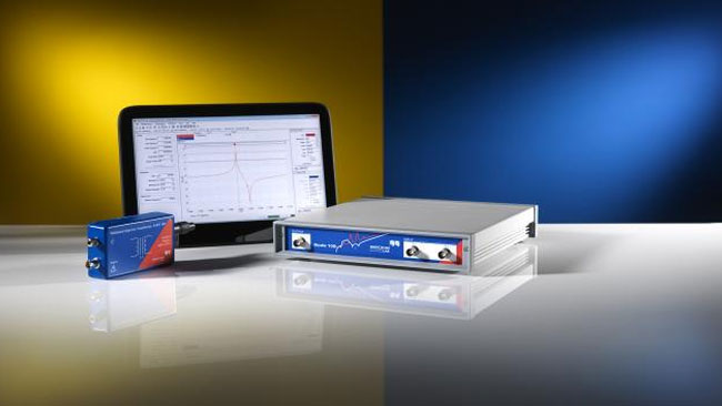
- Low Voltage (< 3.3V): For circuits with low voltage levels, such as those using low-power LDOs, the P2104A 1-port probe is ideal, with minimal signal attenuation. A DC block may not be necessary but could be used to prevent DC loading from the 50-ohm probes. The Bode 100 signal analyzer works well in this range, providing clear impedance data.
- Medium Voltage (3.3V – 50V): For this range, 2-port extended measurements with the P2102A probe are effective. The use of DC blocks becomes crucial to protect the equipment from high voltage inrush and to avoid signal degradation. However, it’s important to note that DC blocks become noisy above 25V and can limit the frequency range of the measurement. Current transformers or modulated e-loads can be used to inject current for more complex 3-port tests, but these require additional equipment, such as power amplifiers.
- High Voltage (> 50V): Testing components at high voltages presents unique challenges, including the potential for damage to the instruments. DC blocks should be used carefully, and 2-port extended range measurements can be achieved with embedded resistors and attenuating probes. Special attention must be paid to the voltage limits of test equipment, particularly in the 50-72V range, where J2111B with a series resistor may be necessary.
An article published on the IEEE using embedded resistors will get up to 14V to a level the VNA can tolerate (with 10x attenuation).
Read Article on the IEEEImpedance Levels for Various Circuits
Impedance testing varies depending on the specific impedance levels of the components being tested. Here’s how you can approach different impedance levels:
- Ultra-Low Impedance (Sub-milliOhm): Testing circuits with ultra-low impedance requires additional power amplification. Typically, 2-port measurements are conducted using the P2102A probe with attenuation. The B-AMP 12 amplifier can be used for source power, and the J2114A Isolator enables measurement of lower impedances with better accuracy.
- Impedance (500mOhm – 5kOhm): For this range, 1-port and 2-port measurements can be used. However, a DC block is recommended when testing voltages above 3.3V to avoid damaging the equipment. With voltages below this threshold, the P2104A probe offers a straightforward solution.
The Challenges and Limitations of 3-Port Measurements
3-port impedance testing has unique limitations. Unlike 1-port or 2-port tests, the setup for 3-port measurements is more complex, requiring careful management of current monitoring and power supplies. The J2112A injector, used with a current probe, allows for precise current measurements but introduces challenges like a ground loop. Additionally, calibrating the setup can be difficult, especially when working with power-sensitive components.
Some specific limitations of 3-port testing include:
- The J2111A injects 25mA of current into the load, which may not be suitable for all references.
- Current probes can introduce noise into the system.
- Unlike 1-port and 2-port measurements, 3-port tests cannot be performed with the power off, making them less useful for analyzing PDN design data without live circuits.
Choosing the Right Equipment
Choosing the appropriate test equipment is crucial for accurate impedance measurements. Different probes, such as the J2102B, J2113A, and J2114A, offer varying performance characteristics depending on the impedance level, frequency range, and the nature of the measurement:
- J2102B: A general-purpose probe ideal for most impedance measurements.
- J2113A: Suitable for measurements below 3kHz and up to 500kHz but not recommended for impedances below 1mOhm.
- J2114A: Best for measuring below 1mOhm, with higher accuracy compared to the J2113A.
Conclusion
Impedance testing is an essential skill for engineers working with power components and systems. Whether you’re testing LDOs, DC-DC converters, or high-impedance circuits, the choice of measurement technique—1-port, 2-port, or 3-port—depends on the specific application, voltage levels, and impedance characteristics. By selecting the right probes and equipment, and understanding the nuances of each test method, engineers can ensure accurate and reliable impedance measurements that lead to better circuit design and optimization.
For more advanced measurements, tools like the Bode 100 or the B-AMP 12 amplifier can further extend the capabilities of impedance testing. With the right setup, engineers can achieve highly accurate and efficient impedance measurements, even in challenging conditions.
Related Products


J2113A Semi-Floating Differential Amplifier – Ground Loop Breaker
Read more: J2113A Semi-Floating Differential Amplifier – Ground Loop Breaker