Co-authored by Picotest and Signal Edge Solutions
Next-Level Measurements: Easier, Faster, and More Accurate
Calibration and measurement accuracy are critical in power integrity and impedance analysis, but they’re often hindered by time-consuming setups, inconsistent connections, and external interference. The new Picotest Component Test Fixture (CTF) addresses these challenges head-on, offering a faster, easier, and most importantly, repeatable measurement process.
By eliminating the need for SMA connectors on mount boards and integrating internal ground-loop isolation, the CTF streamlines your workflow while improving measurement reliability. Whether you’re performing impedance or full 2-port calibration, the CTF ensures consistent results — making it an essential tool for high-precision power-integrity work.
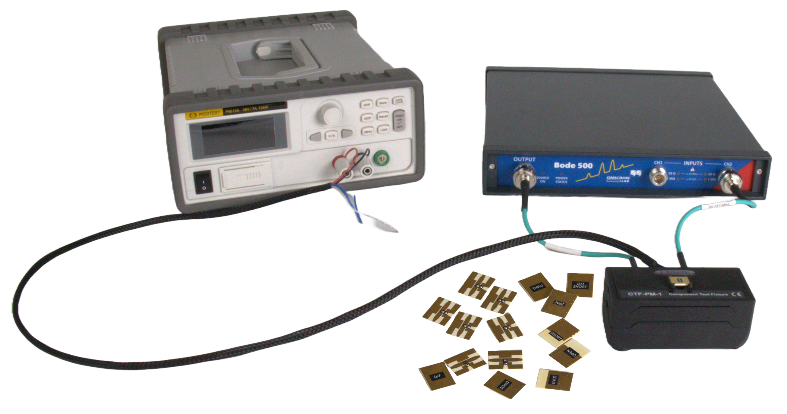
The CTF kit comes with all the mounts necessary for both impedance calibration and full 2-port calibration. This guide focuses on impedance calibration and measurement on the Bode 500 VNA; however, the CTF is compatible with any VNA for full 2-port or impedance calibration.

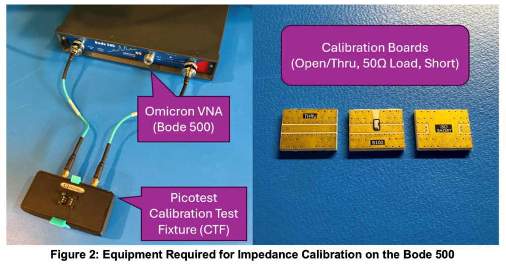
After powering on the Bode 500, with cables connected for calibration as shown in Figure 2, follow the steps below to calibrate your measurement setup prior to making measurements on your DUT. A torque wrench is included to help make sure your connections are secure.
Step 1 — Open a Shunt-Thru Impedance Analysis project
In the Bode Analyzer Suite, if starting a new project, select Impedance Analysis → Shunt-Thru. Otherwise, open your existing project.
Step 2 — Configure source and receiver settings
Set your desired frequency sweep settings and change the Source Level to 0 dBm. Set the Attenuator level to 0 dB and the Receiver Bandwidth to at least half of your start frequency. You may need to use 10 dB attenuation on Channel 2 to avoid channel overload.
Step 3 — Open the User-Range Impedance Calibration
Under the Home tab, select User-Range Impedance Calibration → Perform New Calibration.
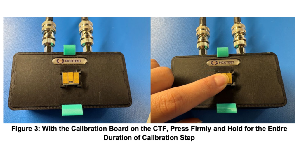
Step 4 — Perform the Open calibration (THRU board)
Place the THRU calibration board face down on the CTF. Press firmly and hold, as shown in Figure 3, then select Start next to Open in the Open/Short/Load calibration. Once complete, you will see “Performed” next to the corresponding step.
Step 5 — Perform the Load calibration (2PM board)
Use the 2PM board with the same method as Step 4.
Step 6 — Perform the Short calibration (ISO SHORT board)
Set the Source Level to 16 dBm (or 13 dBm if using the Bode 100). Perform the Short calibration using the ISO SHORT board, with the same method as Step 4.
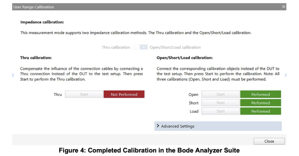
Step 7 — Confirm all calibration steps
Confirm that all three calibration steps were completed, as shown in Figure 4.
Step 8 — Close the calibration screen
Press Close to exit the calibration screen.
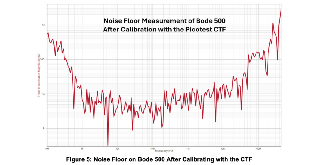
Step 9 — Verify the noise floor
Use the ISO SHORT board to obtain a noise floor measurement. After calibrating with the CTF, this should be in the tens of micro-ohms or better (see Figure 5).
Step 10 — Verify with a known DUT
Always measure a known DUT after completing calibration to ensure you have obtained a proper calibration. Once you’ve confirmed your calibration, you are now ready to measure your component.
Notes on other VNAs
Full 2-port calibration on VNAs such as the Keysight E5061B or the Rohde & Schwarz ZNL follows the same general steps (short, open, load for each individual port) plus an additional thru calibration measurement. For more detailed steps on 2-port calibration, see “2-Port Impedance Measurement using the P2102A Probe and E5061B VNA” on the Signal Edge Solutions site — and explore the P2102A 2-Port Probe on Picotest.
Ready to measure components at pH fidelity?
The Picotest CTF works with any VNA, including the Bode 100, Bode 500, Keysight E5061B and Rohde & Schwarz ZNL. Measure impedance from µΩ to kΩ across DC to 3 GHz, with DC bias up to ±75 V.
How to Measure a DUT Using the CTF and Bode 500
To measure a DUT, mount your component on a CTF mount board and press and hold this board onto the CTF — the same way you held the calibration boards in Figure 3. Begin the sweep by going to the Home tab and pressing either Continuous or Single. Save your waveform by pressing Measurement → New Memory in the rightmost pane of the Bode Analyzer Suite. Ensure you hold your DUT to the CTF for the entirety of the sweep (~30 seconds).
* 1 GHz for Keysight E5061B; 500 Hz minimum for DC bias adapter usage. The Bode 100/500 does not support 2-port-full calibration.
Conclusion
The Picotest Component Test Fixture simplifies and enhances the calibration and measurement workflow on VNAs — delivering faster setup times, more reliable results, and the repeatability required for confidence in analysis. By removing common sources of error, the CTF sets a new standard for impedance and 2-port calibration accuracy when measuring components.
This makes it an invaluable tool for anyone working in power integrity, RF, or high-speed signal environments. In an upcoming post, we’ll explore how the CTF DC Bias Adapter enables accurate and convenient DC bias measurements, expanding its capabilities even further. Stay tuned.
| Feature | Component Test Fixture (CTF) | Universal Calibrator UC10 | P2102A 2-Port Probe |
|---|---|---|---|
| Ease of use | Easiest | Easier | Easy |
| Part mounted on specialized test board | Yes | Yes | No |
| Part-size support | 0201, 0402, 0603, 0805, 1206, 1210, 7343 + custom | 0201–0603 + custom | 0402–1206 + custom |
| Calibration board material | Precision HF | Precision HF | Precision HF |
| Relative accuracy | Most accurate | Most accurate | Most accurate |
| Absolute accuracy (10% limit) | 30 pH | 10 pH | 50 pH |
| Impedance floor | 31 pH | 100 fH | 224 pH |
| Frequency range | DC – 3 GHz+* | DC – 3 GHz | DC – 300 MHz |
| Bode SPICE model capable | Yes | Yes | Yes |
| Compatible with other VNAs | Yes | Yes | Yes |
| Calibration types supported | Impedance/SOL or full 2-port | Impedance/SOL or full 2-port | Impedance/SOL or full 2-port |
| DC bias support (capacitors) | Yes, included, 0–75 V max | Possible with instrument bias | Possible with instrument bias |
| Ground-loop isolation | Included | External unit required (e.g. J2102B) | External unit required |
| Connectors | 3.5 mm | 3.5 mm | SMA / BNC |
| Introductory price | $3,495 | $1,495 | $2,995 |
| Best for… | All-around component measurement, SPICE modeling, simulation correlation | Bode 100/500 users storing calibration across many parts | Quick probe-based testing and browsing |
* 1 GHz for Keysight E5061B; 500 Hz minimum for DC bias adapter usage. The Bode 100/500 does not support 2-port-full calibration.