A frequency response analyzer (‘FRA’) is often used to measure gain and phase plots of control loops (Bode plots), filter responses and general frequency domain transfer functions. The FRA generally has a low impedance, high power oscillator and two, high impedance inputs. In many cases, the input ports are constructed using differential amplifiers. The FRA performs a frequency sweep and records the magnitude of the ratio of the two inputs and the phase shift between the two measurements. These are often plotted as magnitude (in dB) and linear phase as in a Bode plot, but can also be plotted in a Nyquist form. Since the FRA measures both magnitude and phase, it is technically a Vector Network Analyzer (‘VNA’).
An RF VNA (what we will refer to as a VNA) is quite different from an FRA. The VNA generally has two ports, each of which are maintained at a precise impedance. The most common impedance for a VNA is 50 Ohms, though there are also a fair number of 75 Ohm instruments supporting CATV requirements. The 50 Ohm ports are generally used to measure scatter parameters, or S parameters, as they are generally referred to. S parameters were developed to allow the precision port impedance to eliminate the errors caused by probing in higher frequency measurements. The VNA can measure the four transfer combinations referred to as S11, S21, S22 and S12. S11 is the reflection of the input port and S22 is the reflection of the output port. S21 is the gain from input to output and S12 is the gain from the output to the input.
Click here to read the rest of this article.
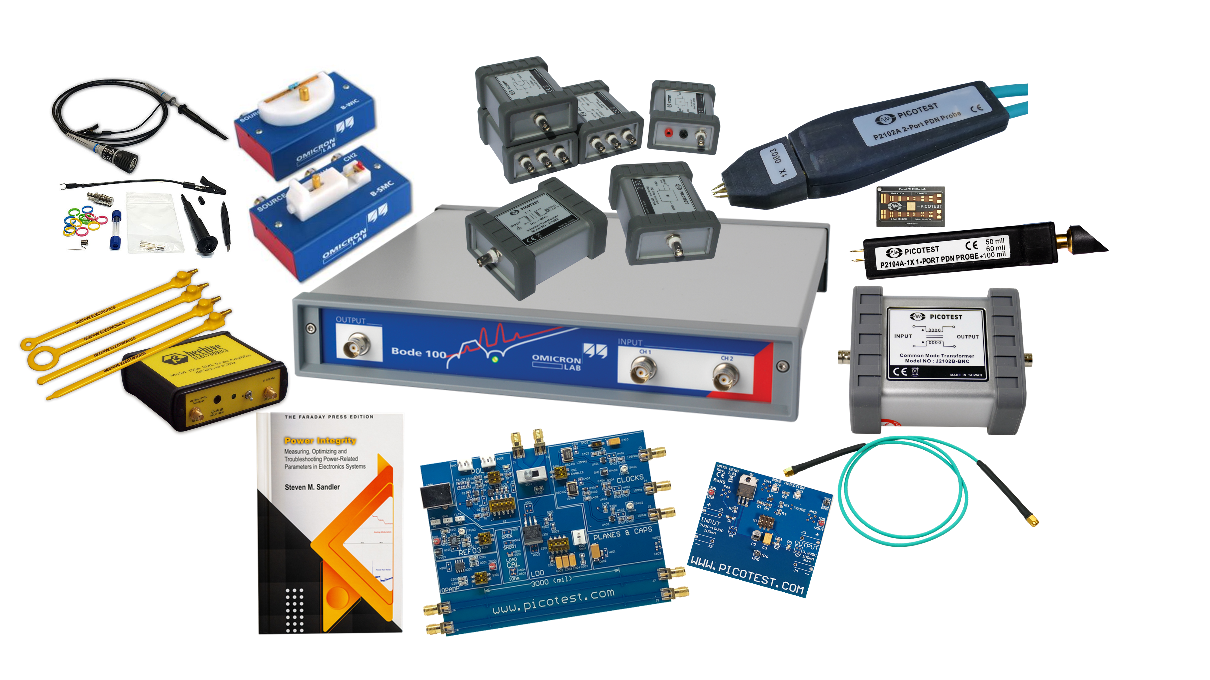
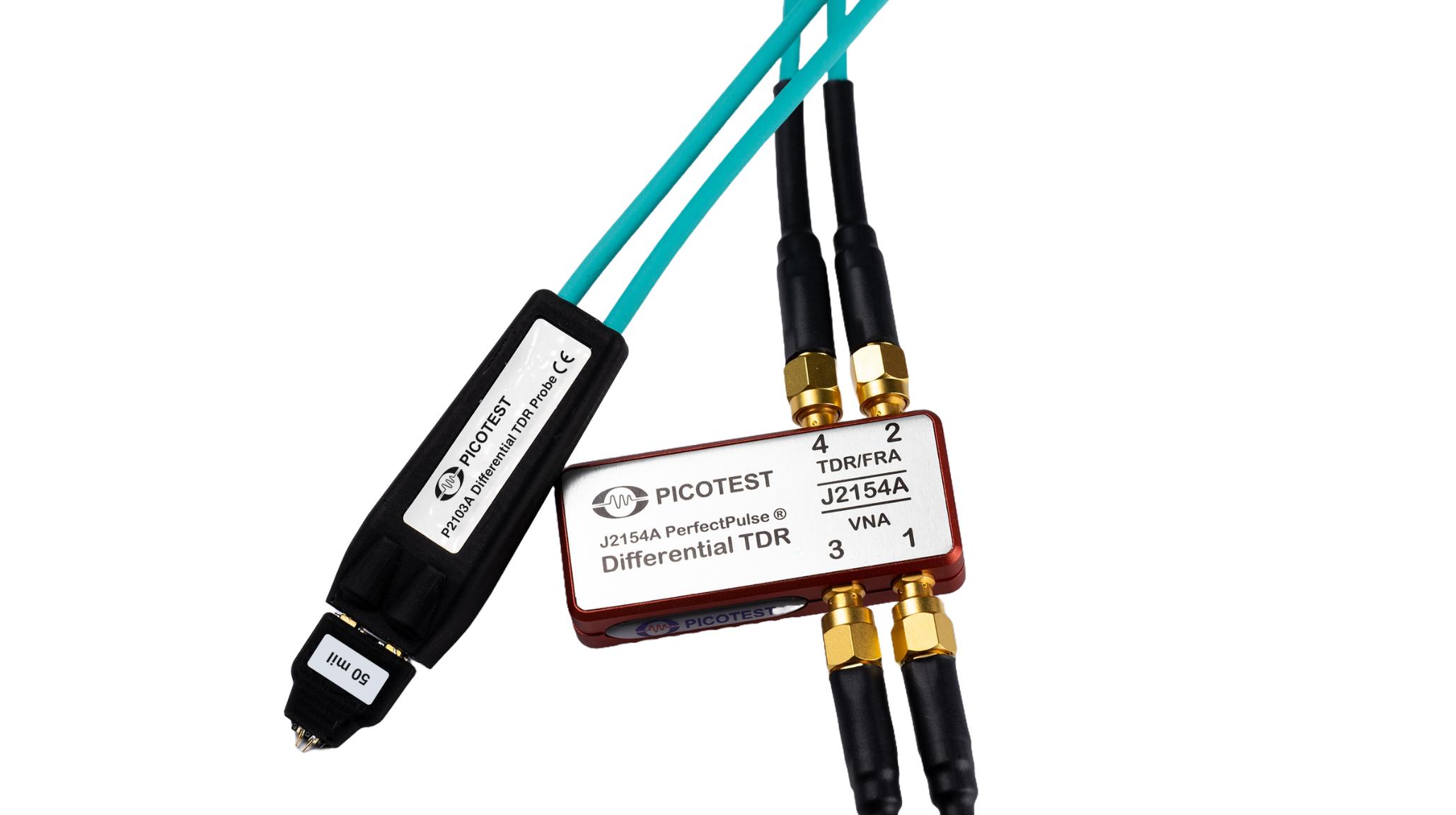
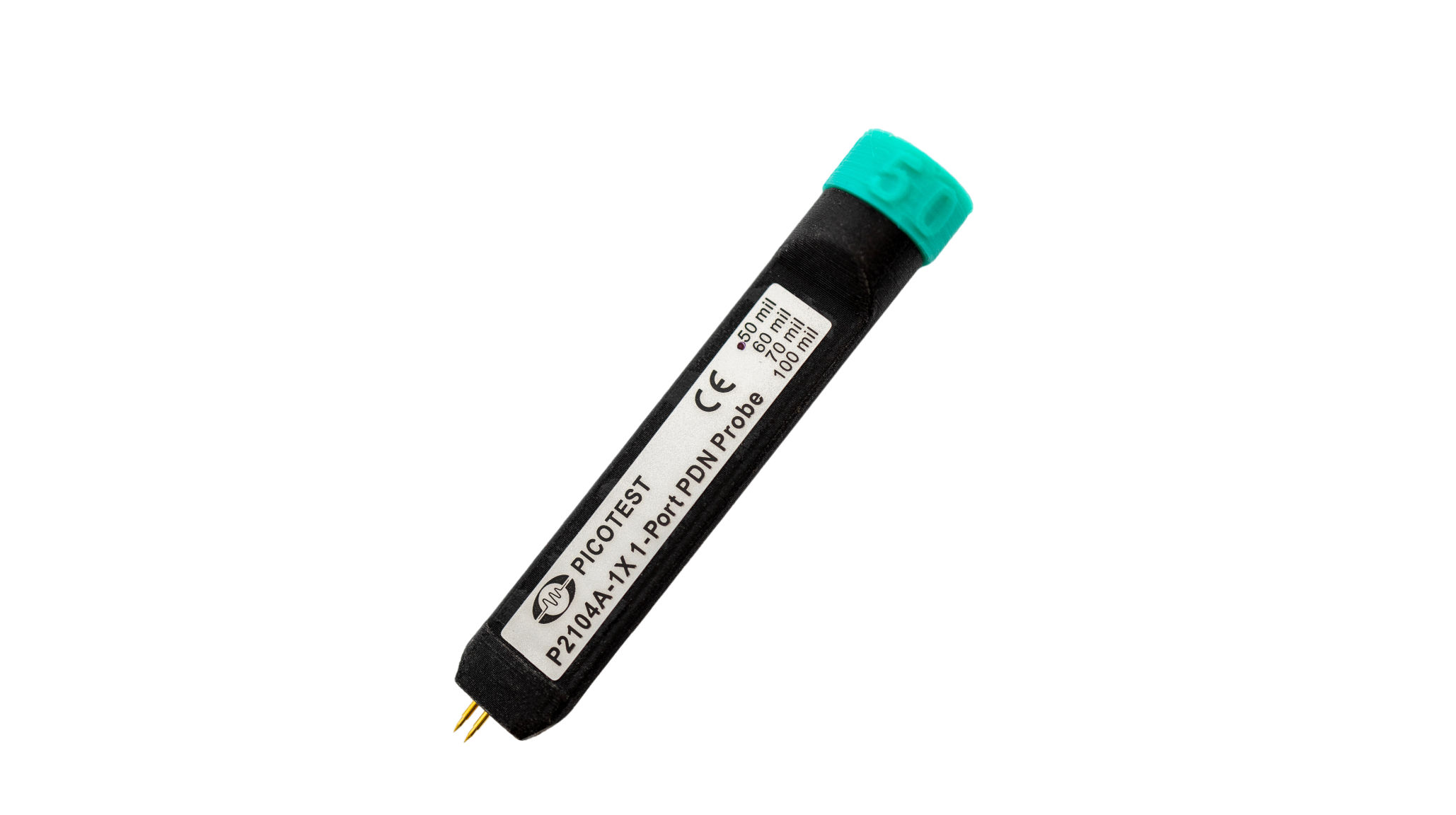
Related Products